Configuring Switch VLANs in OpenWrt
Contents
Translation
This post is also available in Simplified Chinese.
I recently bought a Netgear WNDR4300 router. Normally my computer accesses the Internet through the router’s NAT, but sometimes I need a direct connection to the campus network—for example, when I need to expose a port and cannot figure out the port-forwarding interface. Unplugging the cable from the router every time is too much trouble.
VLANs in OpenWrt
When both a router and a computer need to connect to the campus network, the usual solution is to plug both into a switch and connect that switch to the wall socket. Unfortunately, I did not want to buy another switch, since I was already running out of power outlets.
Looking through OpenWrt’s settings, I found a Switch page under Network that seemed capable of turning the router into a switch. After reading about it, I gained a rough understanding of this router’s internal structure. In addition to the CPU itself, the router contains a switch chip. The router itself effectively has only one network interface; the external WAN port and four LAN ports all connect to the switch chip, and an internal link connects that switch to the CPU.
On the Switch page, each intersection between a VLAN and a port has a drop-down menu with “tagged,” “untagged,” and “off.” Both tagged and untagged add the port to that VLAN; only off excludes it. Their difference is whether the VLAN ID is added to transmitted frames.
After OpenWrt is installed, the switch is already divided into two VLANs, eth0.1 and eth0.2, corresponding to the router’s LAN and WAN networks. eth0.1 corresponds to the VLAN 1 row: ports 1–4 are untagged while ports 5 and 6 are off, so this VLAN contains the router’s four LAN ports. In VLAN 2, only port 5 is untagged, making it the router’s WAN port.
The first column of both VLANs is labeled CPU and is set to tagged. This is the switch-to-CPU link mentioned above. It must be tagged because only one physical link connects the switch chip and CPU; without VLAN IDs in the frames, the CPU could not tell which network a frame came from.
Connecting Directly to the Campus Network
Choose any port from 1–4, change it from untagged to off in VLAN 1, and set it to untagged in VLAN 2. That port is now on the same switch as the WAN port. Note that ports 1–4 on this page are ordered in reverse relative to the four sockets on the back of the router. The page also shows a port 6, although I never found where that port leads.
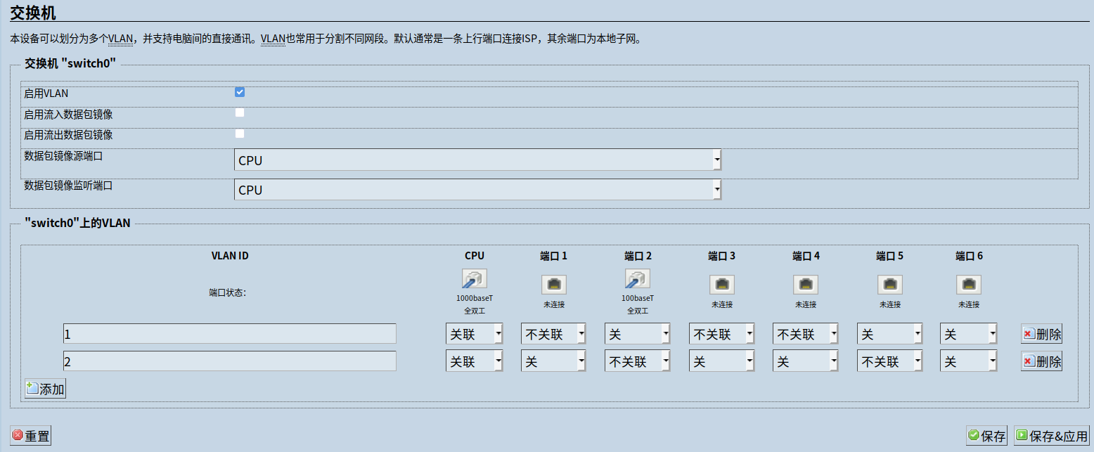
These settings also demonstrate that, other than their colors, the router’s WAN and LAN ports are not inherently different; they merely belong to different switch VLANs. Connect the wall cable to either the WAN port or the port just reassigned, and connect the other one to the computer. The computer is then effectively connected directly to the wall socket.
Follow-up
I later discovered that I had been naive. The L2TP service used at the campus only allows one IP address online per account. As soon as the computer connects through L2TP, the router is disconnected—so this setup cannot actually keep both online at once.